VERICUT Users' Forum
You are not logged in.
- Topics: Active | Unanswered
#1 2012-05-01 01:47:51
- Verifun
- Senior Member

- From: U.S.
- Registered: 2005-03-31
- Posts: 351
- Website
Driven point for turning tools imported via CAD models
Hi folks...
This is making me to pull a hair I don't have out... :?
We have the STEP converter option and it works very well... and kudos to R&D to allow the simulation of negative inserts that does not necessarily have their cutting face parallel to the ZX plane... this was one of the best things one can get with this STEP interface because the software intersects the insert model with the ZX plane and gets the insert boundaries as a sketch... this sketch is used internally as the cutter shape satisfying the condition that the turning insert needs to lie on the ZX plane, however the cutter is graphically Ok and the user does not have to create false 3D inserts lying on the turning plane anymore... Great!
The problem is that ALL turning tools in our MillTurns are programmed with their driven point in the center of the nose radius... we're forced to adopt this method as our CAM system (Pro/NC) is unable to output the correct toolpath if the programmer tilts the B-Axis of the MillTurn... the only way to get a correct output in every angle is to use the parameter OUTPUT_POINT as CENTER in Pro/NC so Pro/NC offsets the entire toolpath by the nose radius value in all directions... if you tilt the B axis, no problem will occur because the center of rotation never changes when the OUTPUT_POINT as CENTER is used in Pro/NC...
The thing is that we also have a setting in our machine settings in Pro/NC (Workcell) that output the contour on the profile when we use cutter compensation (CUTCOM), so in this case what goes to the NCL is the real profile without any offsets applied to it... when it's a roughing toolpath for example (no CUTCOM), the toolpath is offset by the algorithm... for a finish profile, the real profile goes to the NCL file because we usually cut these using CUTCOM...
Any lathe control allow the operator to define the location of the control point for a given tool... most shops set the control point of a turning tool in the quadrants of the nose radius, so when it comes to diameters (X coordinates) and vertical faces (Z coordinates) no compensation takes place... if the machine cuts a taper with CUTCOM activated, then the CNC control compensates the tip...
Well, in our case, we also set the location of the driven point in the CNC, but we set it as the position 9 (Center of the nose radius in most controls), so when we have to finish a profile the control compensates the tool by offsetting both diameters and faces by the value of the nose radius.
Let's suppose we have this scenario:
Final O.D. = 300mm
If we have a turning tool with a nose radius of 1.2mm and we want to finish this O.D without CUTCOM, we would have to program it as 302.4 (This is what Pro/NC already does for us)
If we use CUTCOM, then the coordinate that goes to the tape file is 300mm, and the control knows the driven point is the center of the nose radius and offset the tool accordingly when G4x is used.
Got it?
So here goes the million dollar questions: ![]()
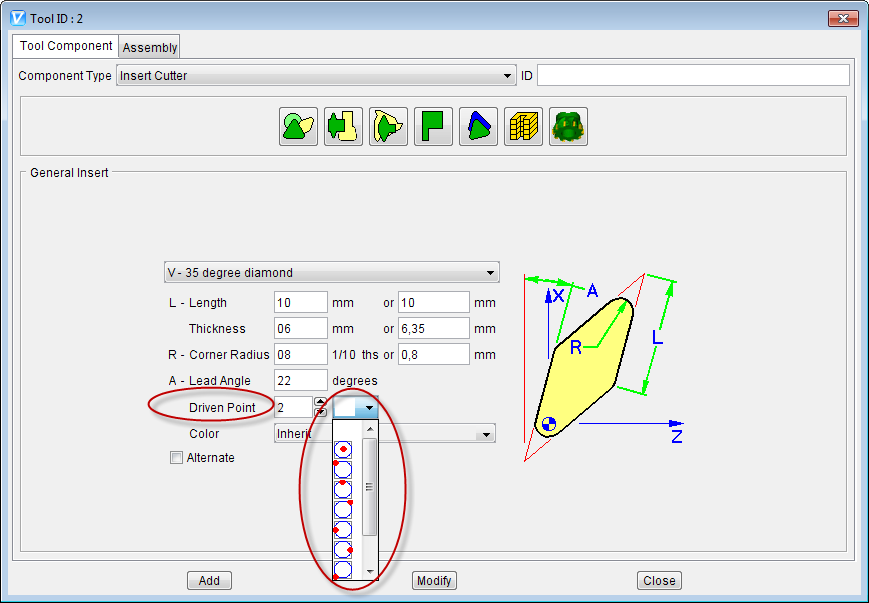
So for an insert created using the insert dialogs, how can Vericut know where my driven point is? I know we have the driven points in the pic below, but once I define them in the insert dialog and later enter in the insert definition dialog again, I don't see the driven point icon set like as I left it, although it's correctly located graphically in the view. Is this a bug? (The loss of the definition?)
And now and more importantly: When working with imported CAD models (STEP for example), the inserts are imported properly but what the Vericut algorithm does is to intersect the insert model as I mentioned in the top and extract the outline of the cutter insert... So... how one defines the control point as the center of the nose radius in a sketched insert, and how Vericut can associate the location of this driven point like the CNC control does so it compensates the nose radius accordingly like the control does when the driven point is located in a place other than the usual definition, that usually is the driven point at the tangent of the X/Z quadrants?
I really need to understand this stuff... all our turning tools needs to be driven by the center of the nose radius and we use a bunch of CUTCOM too...
Sorry for the long message... I'm really inspired today... ![]()
Thank you in advance,
Daniel
Daniel Santos
Offline
#2 2012-05-02 13:44:20
- MustaphaC
- VERICUT Specialist

- From: Le Mans, France
- Registered: 2004-10-14
- Posts: 130
- Website
Re: Driven point for turning tools imported via CAD models
Hi Daniel,
A quick answer to your 2 questions:
- The "Driven Point" pics only helps to find the right values for the Driven Point. Once you add the tool there is no more relation between the values and the "picture". Because the user can edit the driven point values after using the graphic pics and these new values could even be something out of the 9 positions! So it is not a bug, it working as designed
- To have VERICUT take into account the cutter compensation values for imported CAD tools, for the moment, you have to move the whole assembly in order to have the center of the insert radius to correspond to the tool manager origin. Then add driven point with corresponding offset (for example -1.2 0 -1.2). And finally add a table for the "Tool Nose Compensation" with the same values as Driven Point. If you have further question on this subject please send an email to your CGTech representative with an example and what you want to achieve, thanks!
Mustapha
Offline
#3 2012-05-02 20:39:15
- SergeV
- Senior Member

- From: Irvine, CA
- Registered: 2004-10-08
- Posts: 507
- Website
Re: Driven point for turning tools imported via CAD models
I have built a few tool assemblies from STEP assemblies I downloaded from the Sandvik and Kennametal websites. The tool assembly is generally built from a qualified position on the back of the holder, generally at the gage point. The catalog will generally display the qualified dimensions from the back of the holder to the driven point. You then have 2 choices:
1) build the tool as-is with the origin of the tool at the gage point and enter the qualified distance to position the driven point (Gage point should be 0,0,0)
2) Shift the tool assembly by the qualified dimension, the driven point is then 0,0,0 and the gage point is moved by the qualified distance.
both method get the same results in most case.
Offline
#4 2012-05-02 23:33:34
- Verifun
- Senior Member
- From: U.S.
- Registered: 2005-03-31
- Posts: 351
- Website
Re: Driven point for turning tools imported via CAD models
Hi folks,
Thanks for the replies...
I was unable to make you understand this thing... I'm opening a case with my rep to figure this out with you...
Tks
Daniel
Daniel Santos
Offline
#5 2012-05-03 16:01:29
- SergeV
- Senior Member
- From: Irvine, CA
- Registered: 2004-10-08
- Posts: 507
- Website
Re: Driven point for turning tools imported via CAD models
in 7.1, you can import a full STEP assembly (this requires the STEP CAD interface). in the manufacturer's catalog, you will generally find the location of the driven point. For most turning tools (I will clarify after) all that matters is the distance between the driven point and the gage point (point that connects with the Tool component on the machine).
The exception is when you have tool nose compensation or that you are turning with the tool loaded on a rotary head, in those cases you have less flexibility on how you build your tools. The tool origin must be at the center of the cutter radius. The distance between the tool origin and the driven point will be used to compensate correctly.
Steps:
1) Import tool assembly
2) define driven point
3) define gage point
4) move each component of the tool assembly so the origin (axis system) is at the center of the radius.
If you build the tool with parametric inserts, the origin is already at the center of the tool radius.
Offline
#6 2012-05-03 16:51:50
- Verifun
- Senior Member
- From: U.S.
- Registered: 2005-03-31
- Posts: 351
- Website
Re: Driven point for turning tools imported via CAD models
Serge, thanks!
The question is: How can we setup Vericut to compensate the radius just like the control does?
I mean: In the control we have the numbers from 1 up to 9 and depending on which number we use for a offset the control will offset the tool in a certain way...
What's the relation in Vericut between these numbers and the driven point? How Vericut changes the way it compensates the contour like the control does as said above?
This is what is not clear yet... I know we can put driven points everywhere... but I don't know how the SW handles the cutter positions like the CNC...
Tks
Daniel
Daniel Santos
Offline
#7 2012-05-03 17:17:59
- SergeV
- Senior Member
- From: Irvine, CA
- Registered: 2004-10-08
- Posts: 507
- Website
Re: Driven point for turning tools imported via CAD models
VERICUT will compensate the path like your machine. With parametric inserts, you have a choice of the 9 possible driven points, as you define the insert, select the desired point and it will be created when you press Add. You can also open an insert you defined before select the driven point and select Modify.
Offline
#8 2012-05-03 17:32:45
- Verifun
- Senior Member
- From: U.S.
- Registered: 2005-03-31
- Posts: 351
- Website
Re: Driven point for turning tools imported via CAD models
Thanks again Serge,
What about imported CAD models where the insert is skecthed?
Daniel Santos
Offline
#9 2012-05-03 17:40:15
- SergeV
- Senior Member
- From: Irvine, CA
- Registered: 2004-10-08
- Posts: 507
- Website
Re: Driven point for turning tools imported via CAD models
you need to build the sketched insert from the center of the radius. Then you define the position of the Gage point manually, by shifting it from the radius value in X and Z. We only have an automatic method for the parametric inserts.
Offline
#10 2012-05-03 18:14:00
- Verifun
- Senior Member
- From: U.S.
- Registered: 2005-03-31
- Posts: 351
- Website
Re: Driven point for turning tools imported via CAD models
Ouch... I did bet with a workmate that our new STEP converter option would save our bacon... I don't know how to tell him he was right... :oops:
Can I use this post to submitt an official enhancement request for this? :?:
Tks
Daniel
Daniel Santos
Offline
#11 2012-05-03 18:31:02
- SergeV
- Senior Member
- From: Irvine, CA
- Registered: 2004-10-08
- Posts: 507
- Website
Re: Driven point for turning tools imported via CAD models
1st thing, the functionality is there, you can simulate the compensation but with a bit of configuration in Tool manager. The interface will still save you a lot of time building the tools since you are using the 3D models directly.
We are working on improving the process within the Tool Manager for future releases but also working directly with large tool manufacturers to include some useful parameters into their STEP assembly.
Since I do not know all you need and your usage of the CAD interface, it would be better if you reached out to your local CGTech office and they could look at your examples and suggest the best plan of action.
Offline
#12 2012-07-08 14:31:56
- ecapatto
- Member

- Registered: 2010-05-27
- Posts: 11
Re: Driven point for turning tools imported via CAD models
I and Daniel did a small test using a tool with the control point at the tip of the tool (that should be the usual application for more than 80% of all users) and a machining of 5 bodies with different positions for B axis using and don't using the flash. The obtained diameter were wrong on the simulation using G41/G42 compensation. This means that, at least at seems, VC doesn't handle the Driven Point when we change the B axis position.
On our real machine the tool needs to be defined with a "original cutting position" (means the tool at the B axis = 0) and then when we change the B axis position the control changes also the cutting position, so in the tool management we can see the "original cutting position" (tool original driven point) and the "actual cutting position" (actual driven point to that specific B axis position).
Daniel question is not about how difficult is to be defined the control point, but how VC handle this once the definition of the "tool control point position" is just a <a class="inlineAdmedialink" href="#">cosmetic</a> thing. Of course that enhancements on the definition of the control point position (values definition) could be really interesting once we'll import thousands of tools on our data base. But at this moment what's really matter to us is to know how make this happens at the right way, I mean, a turning tool with the control point at the tip, with different positions of B axis and active cutter radius compensation we need to obtain the same machined diameter.
More one thing, when the tool driven point is at the center of the tool nose radius this works just fine, and of course it should do once the tool is understandable as a rounded tool no matter what the position of the B axis. It's just as you hold a coin at its center and rotates it, the edge will be at the same position every time.
Thank you by the advance
E.Capatto
NC Programer - CAV Support - Software Developer
GE Oil and Gas Brazil
Offline
#13 2012-07-09 07:17:28
- MustaphaC
- VERICUT Specialist
- From: Le Mans, France
- Registered: 2004-10-14
- Posts: 130
- Website
Re: Driven point for turning tools imported via CAD models
This is typically handle by "DynamicToolTipOnOff" macro. But current with an imported CAD tool the insert corner radius is not defined. DynamicToolTipOnOff can only work with "parametric" inserts
Mustapha
Offline
#14 2012-07-09 12:17:20
- ecapatto
- Member
- Registered: 2010-05-27
- Posts: 11
Re: Driven point for turning tools imported via CAD models
Thank you MustaphaC,
Is that a way to work around this :? ? If not I guess that the cad interface is not so useful to us as we were thinking once we'll need to import the holders but the inserts will need to be defined in the parametric way :cry: .
Now I make the Daniel's words as mine, can we use this forum to suggest a software enhancement on this direction?
Cheers,
E.Capatto
NC Programer - CAV Support - Software Developer
GE Oil and Gas Brazil
Offline
#15 2012-07-09 12:33:21
- MustaphaC
- VERICUT Specialist
- From: Le Mans, France
- Registered: 2004-10-14
- Posts: 130
- Website
Re: Driven point for turning tools imported via CAD models
This enhancement Request is already in CGTech SCR system, it is just a priority issue now...
Mustapha
Offline